
 0
0



- Home
- Knowledge
- Equipment Selection
- What is Flame Treatment? Polarizing PE/PP to Prevent Ink Adhesion Failure
What is Flame Treatment? Polarizing PE/PP to Prevent Ink Adhesion Failure
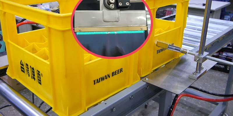
Comprehensive Guide to Flame Treatment Technology: The Key to Polarizing PE and PP Plastics to Prevent Ink Adhesion Failure
In industrial surface printing and coating workflows, PE (polyethylene) and PP (polypropylene) are typical high-molecular non-polar materials with exceptionally low surface energy. Currently, photocurable UV inks on the market cannot adhere firmly to untreated PE or PP bottles and substrates without modification. To break this non-hydrophilic physical barrier and eliminate ink peeling or adhesion failure, a polarization pre-treatment must be conducted prior to printing. The most effective and economical mainstream choice in the industry is "Flame Treatment."
Unlocking the Mechanics of Flame Treatment: A Split-Second Polarization Driven by Free Radicals
How does a flame modify a plastic surface? It is a precise chemical transformation:
- Instantaneous Free Radical Oxidation: A high-temperature flame is highly enriched with active free radicals such as O, NO, OH, and NH.
- Chain Scission to Introduce Polar Groups: When the flame passes over the plastic surface, it extracts hydrogen atoms from the PE or PP chains. This triggers surface oxidation via a free radical mechanism, introducing oxygen-containing polar functional groups and causing chain scission.
- A Complete Shift in Hydrophilicity: This reaction successfully transforms the non-polar plastic surface into a polar structure, significantly improving its wettability and constructing a rugged anchoring foundation for ink molecules.
📊 Industrial Surface Tension Comparison Rule of Thumb:
The surface tension of water is approximately 72.5 dynes/cm, while conventional inks range between 25–50 dynes/cm. Following flame treatment, the surface energy of PE and PP must **reach at least 45 dynes/cm** to completely satisfy the critical threshold required for UV ink molecules to properly wet out and cross-link securely.
Flame treatment machine operation instruction video demonstration
Core Process Calibration: Golden Flame Treatment Parameters

Most production lines utilize fuel gas (LPG/natural gas) as the combustion source. To achieve the ideal treatment depth (approx. 40–90Å) without deforming the product, equipment specifications and process parameters must be strictly controlled via the following configurations:
- Air-to-Gas Mixture Ratio —— Air : Gas = 7 : 1
The line must be calibrated to achieve a crisp blue-violet flame. This indicates the highest flame temperature, reaching approximately 1270°C, which is the golden state for optimal surface polarization. - Flame Structure Control —— Inner Cone Length: 6 - 19 mm
A stable inner cone ensures high and uniform energy output, preventing flame drifting that can cause localized overheating or inconsistent treatment profiles. - Safe Working Distance —— Inner Cone Tip to Object Surface: 10 - 15 mm
This exact distance represents the boundary layer where the concentration of active free radicals is highest and the surface oxidation effect is at its absolute peak. - Dwell/Contact Time —— LDPE: 1 - 2 seconds / HDPE: 3 - 4 seconds
Exposure timing must be highly precise. Insufficient contact fails to polarize the material, while excessive exposure causes the plastic surface to melt and deform. - Part Rotation Speed —— 100 - 150 RPM
Rotating cylindrical or round bottle shapes at a steady speed guarantees uniform heat exposure, resulting in consistent 360-degree polarization across the entire surface area.
How to Verify Polarization Success: Two Reliable Field Testing Methods
How do production engineers objectively confirm whether the flame treatment has hit the required specifications? The following two mainstream inspection methods are widely used on the factory floor:
- Dyne Test Pen Method: Apply a standardized dyne solution (such as a mixture of 35% ethylene glycol + 65% formamide) or a calibrated dyne pen across the treated zone. Observe whether the liquid film shrinks or beads up to directly read if the surface tension value exceeds 45 dynes/cm.
- Industrial Water Immersion Test (Most Popular for Production Lines):
- Completely submerge the flame-treated PE or PP bottle in clean, pure water.
- Withdraw the bottle vertically and let it rest for a brief moment (approx. 10 seconds) to allow excess water to drain away naturally.
- Result Evaluation: If the target surface is covered with a uniform, continuous film of water that remains intact for over 15 seconds without breaking up, it demonstrates excellent hydrophilicity. The treatment is successful, and the part can proceed directly to printing. If the water film breaks instantly, recedes, or beads up like "rainwater on a lotus leaf," the polarization has failed. The operator must immediately adjust the air-to-gas ratio, distance, or contact timing.
Factory Operational Safety: Igniting and Balancing Your Flame Curing System
To guarantee operator safety and lock in the most stable blue flame configuration, always execute setup adjustments in this exact sequential order:
- Inlet Air Pressure Regulation: Adjust the incoming regulator on the supply side to precisely lock the inlet air pressure at 2 KG.
- Air Flow Perception: Fine-tune the air flow valve. Safely place a hand near the flame nozzle assembly until you can perceive a "faint, gentle stream of air blowing out."
- Electronic Ignition Test: Press the "Ignition Test Button" on the control HMI console to confirm the high-voltage spark plug arcs cleanly and smoothly.
- Introducing Fuel Gas: Fully engage the main gas supply valve, then gradually open the gas flow control valve until the flame successfully ignites.
- Calibrating the Golden Blue Flame: Carefully adjust both the air flow valve and gas flow valve simultaneously. The resulting flame must display a steady, crisp blue hue. (⚠️ A yellow-red flame must be avoided under all circumstances).
- Red Flame Troubleshooting: A reddish flame signifies an incomplete combustion state caused by **insufficient air flow or an excessively rich gas volume**:
- If a smaller overall flame is required: Throttle the gas flow control valve downward.
- If a larger overall flame is required: Turn the air flow valve upward to feed more oxygen into the mix.
FINE CAUSE Selection: Industrial-Grade Flame Treatment System Solutions
Achieving exact process metrics requires heavy-duty machinery engineered for ultra-precise gas-mixing execution. To satisfy varied geometry requirements and high-throughput automated lines, FINE CAUSE offers the following industrial flame pre-treatment systems:
1. FIR1 Conveyorized Dual-Side Flame Treatment Machine (Optimized for High Throughput) ↗
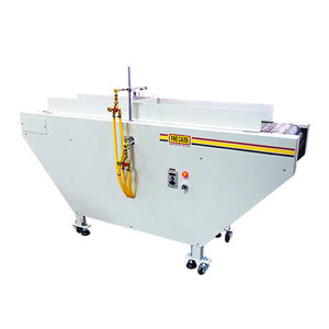
Production Highlight: Specially engineered for rapid part feeding and simultaneous double-sided polarization. Features an adjustable conveyor speed that seamlessly integrates into upstream automated production cells.
- High-Flexibility Adjustment: Flame height, working distance, and burner angles can be freely tailored to fit varied workpiece dimensions.
- High-Temperature Resistant Conveyor: Built with a premium stainless steel wire mesh belt that operates continuously under high thermal loads without warping, guaranteeing a prolonged service life.
- Dual Burner Productivity: Outfitted with one 25cm industrial-grade flame burner on the top and one on the bottom. Parts are fully polarized on both sides in a single pass, doubling throughput. Burner sizes can also be customized to match your product footprint.
2. FIR-2 Customized Automated Surface Treatment System (Three-Axis Versatility) ↗
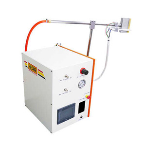
Production Highlight: An intelligent, custom-engineered flame pre-treatment solution purpose-built for complex geometries and multi-material applications (plastics, metals, glass). Ideal for high-precision screen printing, painting, and lamination lines.
- PLC-Driven Smart Control Hub: Controlled via an industrial-grade PLC microcomputer system and featuring our proprietary "Precision Blue Flame Technology." The gas mixture is strictly managed to ensure exceptional dyne uniformity.
- Three-Axis Adjustable Burner Assembly: Features a rugged, three-axis adjustable burner mechanism, making it effortless to maintain the golden 10–15mm working distance over complex, 3D curved surfaces.
- Safe Automated Ignition: Equipped with a one-touch auto-ignition sequence and electronic flame-out safety monitoring sensors to ensure hazard-free plant operations.
- Extensive Custom Engineering: The main console features a compact footprint of L47 * W42 * H35 cm (burner fixture housing: L72 * W59 cm). Burners are available in 10cm, 20cm, or custom configurations tailored exactly to your product geometry and floor space constraints for seamless inline automation.
Conclusion: Choose FINE CAUSE for a Flawless Pre-Print Adhesion Process
In industrial surface processing, ink peeling is rarely a failure of the ink itself—it is usually caused by a lack of precision during pre-treatment. From managing the air-to-gas ratio for a stable blue-violet flame to executing scientific dyne-level verification, FINE CAUSE provides more than just top-tier screen printing machinery and consumables; we deliver comprehensive engineering expertise. Contact us today to schedule an in-house sample testing session at our laboratory, and let our engineering team back your manufacturing line with quantifiable, data-backed adhesion performance!


Article Classification
Recent Articles
- How to Choose Between a Plasma Treatment Machine and a Corona Treatment Machine?
- How to Choose the Right Automation Equipment to Build an Efficient Production Line
- Corona Treatment
- What is Flame Treatment? Polarizing PE/PP to Prevent Ink Adhesion Failure
- How to Choose an Industrial Mixer: Planetary vs. Centrifugal